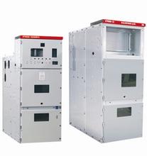
KYN28-24KV switch cabinet
- Brand:
- Type:

First, product overview:
KYN28-24 switch cabinet, power distribution device is 3.6 ~ 40.5kV three-phase AC 50Hz single busbar and single busbar system, mainly used in power plant, generator power supply, industrial and mining enterprises and electric power distribution business system two substation power transmission, high pressure and large motor starting control. Protection, monitoring, this equipment can meet the requirements of IEC298, GB3906 and other standards, can prevent the load push-pull circuit breaker, to prevent the grounding switch is in the closed position when closing the circuit breaker, to prevent mistakenly charged compartment, prevent power misconnecting zone interlock function of grounding switch, can be used with VHL (VS1) -24 vacuum circuit breaker, VD4 vacuum circuit breaker with ABB, and, it is a kind of switch cabinet with superior performance.
Conditions of use
3.1 normal operating conditions
A) ambient air temperature: 5 degrees C~+40 degrees C;
B) altitude: no more than 1000m;
Relative humidity: daily average relative humidity is not more than 95% months average relative humidity is less than 90% c;
D) earthquake intensity: no more than 8 degrees;
E) no fire, explosion danger, serious pollution, chemical corrosion and violent vibration of the place.
3.2 special conditions of use:
In the normal use of more than IEC298 under the conditions, by the user and manufacturer consultation
Structure and working principle
Switch device consists of a cabinet body and set spare parts (namely the hand car) of two component into, the cabinet body divided into four single compartment, shell protection grade IP4X, each cell and outside the circuit breaker room door opened protection grade is be drew out. With overhead into the line, cable wire inlet and outlet and other functional programs, by arrangement, combination can become various alternatives in the form of the distribution device. The switching equipment can be from the front to the installation, debugging and maintenance, so it can be formed back to back double array and installed on the wall, to improve the security of switchgear, flexibility, reduce the area.
Switching equipment of the shell is made of imported aluminum zinc coated steel sheet processed by CNC machine tool, take the multi folding technology. This makes the whole cabinet body not only has high precision, strong anti corrosion and antioxidation, and due to the adoption of the folding process, the cabinet than other similar equipment cabinet as a whole
Light weight, high mechanical strength, beautiful appearance. Cabinet with assembled structure, formed by the rivet nuts and high strength bolt connection. This makes the production cycle is short, the common parts of strong, covers an area of small, easy to organize production.
1, wall bushing 2, analog bus 3, nameplate, lighting lamp 5, mistress line 6 contact box 7, the current transformer, a cable 9, grounding bus 10, secondary chain assembly 111, insulating plate bending 12, valve mechanism of 13, circuit breaker handcart 14, insulator 15, insulation board 16, 17 heater, and the cabinet body frame
Fig. 1 Structure of switch equipment
5.2 hand car
Handcart frame also used thin plate by CNC machining after assembled. Vehicle and the cabinet Hugh insulation coordination, mechanical interlocking safety, reliable and flexible. According to use the same hand car branch circuit breaker handcart, voltage transformer hand trolley, metering handcart, isolation in military vehicles, with the specifications of the handcart percent
Hundred interchangeable. In military vehicles in the cabinet body is disconnected position, test position and a working position, each position are respectively positioning device, to ensure reliable interlocking must according to the interlocking anti misoperation procedures. All kinds of hand car are made of wire rod shaking promote exit. Easy operation, flexible, suitable for
In various operator on duty. In military vehicles when the need to remove the cabinet, with a special transport vehicle, you can easily removed, for a variety of inspection, maintenance; and the use of built-in, small volume of the whole car, inspection, and maintenance are very convenient.
Disposition of the work only in the car to push to completely disconnect circuit breaker circuit breaker handcart is equipped with a vacuum circuit breaker and other auxiliary equipment. When the truck running car transported into the cabinet room, they can be reliably locked in position (position) and the cabinet position display lights will display the location, and only in the lock, it can shake the propulsion mechanism, the handcart working position. The hand position, the pushing handle does not shake, the corresponding position display lights will show its location. The hand car mechanical interlocking can reliably guarantee the hand car position or test position (exit position), circuit breaker to switch on, and only the circuit breaker switch state, the hand of the car to move.
5.3 compartment
The main electrical components of the switchgear are in the separate compartment, i.e., the circuit breaker, the bus bar, the cable compartment, the cable compartment, and the relay instrument room. The protection level of each compartment is up to IP2X
. in addition to the relay room, the other three compartment, respectively, of the pressure relief channel. Due to the adoption of the built-in form, position of the cable compartment is greatly increased, so equipment can connected with the multi-channel cable.
5.3.1 circuit breaker room B
Isolation on both sides of the installation of the track, for hand car 13 in the cabinet by the off position test position to move to the working position. Static contact box 6 and partition 12 (valve) installed in the cab rear wall. When the car from the off position to move to the working position in the process, upper and lower static contact box on the live
The door with the handcart linkage, open automatically at the same time. When to move in the opposite direction valves automatically closed. Until the hand car back to certain position and completely cover the static contact box, forming effective isolation. Also because, under the valve is not linked, in maintenance, lock valve of the charged side, so as to ensure the inspection
Repair and maintenance personnel do not touch the charged body. When the circuit breaker room door is closed, the hand cart can also operate.
Through the door observation window, it can be observed that the indoor hand car is located in the position, closed, the gate display, energy storage condition.
5.3.2 bus isolation
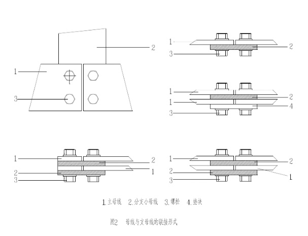
Mistress line 5 is single spliced through connection, shown in Figure 2. The branch bus and static contact box fixed. Mistress lines and tie bus copper bar of rectangular cross section; high current load for the double busbar linked together. Branch bus through a bolt connection in static contact box 6 and mistress, line,
Need other support. For special needs, bus using heat shrinkable sleeve, the bolt connection insulation sleeve and the end cap cover. Adjacent cabinet bus bar casing 1 is fixed. This connection bus between the retention of air cushion, if there is internal fault arc, prevent through melting. Casing 1 can effectively the fault isolation and not to other cabinet spread.
5.3.3 cable compartment C
Switch equipment with built-in and cable room space larger. Current transformer 7 are installed in septal ventricular posterior wall. The truck 13 and withdrawable type horizontal baffle away, construction personnel can enter the cabinet installation and maintenance from the facade. The indoor cable cable connecting conductor, each phase can and 1 ~ 3
Single core cable. When necessary, each phase can and take 6 single core cable. Cable connection to the cabinet bottom preparation slotted detachable type non-metal sealing plate or non-magnetic metal sealing board, to ensure that the construction is convenient.
5.3.4 relay instrument room
Relay instrument indoor installation of relay protection device, instrument, charge indicator, and the special requirements of the secondary equipment. Control line laying in enough space in the slot, and a metal cover plate, the second line and high voltage isolation room. The slot at the left side is a small line control and leads to the reservation, switch cabinet inside the small line laying on the right side. On the roof of the compartment of relay instrument also left to facilitate the construction of the small bus through hole. When wiring, meter chamber top cover for flip, easy to installation of busbar.
5.4 to prevent misuse of interlocking devices
Switchgear equipped with a safe and reliable interlocking device, fully meet the "five defense" requirements.
The 5.4.1 instrument room door is equipped with the prompt button or the KK type switch, to prevent the error, and to break the circuit breaker.
5.4.2 circuit breaker in the test or operating position, the circuit breaker to carry out the operation of the closing,
But in the breaker, hand car can not move, prevent the load error push-pull circuit breaker.
5.4.3 only when the grounding switch is in the closing position, the breaker handcart to from the test / broken open position moves to the working position. Only when a circuit breaker handcart is in the test / disconnected position, grounding switch to closing operation (grounding switch with voltage display device). This realization of the preventing charged misconnecting grounding switch and prevents the grounding switch is in the closed position when closing the circuit breaker.
5.4.4 grounding switch is in a closing position, the door and the rear closing plate can not be opened, to prevent into live space.
5.4.5 circuit breaker does in the test or working position, and no control voltage, only manual switch, not closed.
5.4.6 circuit breaker in the work position, the two plug is locked can not be removed.
5.4.7 the cabinet can be installed electric interlocking
The switching device can also be equipped with an electromagnetic locking device on the grounding switch operating mechanism to improve the reliability, and the order is selected according to the demand of the user.
5.5 pressure relief device
In circuit breaker handcart room, above the busbar chamber and a cable chamber are equipped with pressure relief devices, when the internal arc fault circuit breaker or a bus, with arc, switch cabinet internal pressure increases installed on the door special sealing ring to seal up the front of the cabinet, is arranged on the top of the discharge pressure metal plate will be opened automatically, release pressure and discharge gas, in order to ensure the safety of operating personnel and switchgear.
Two position interlock between 5.6 plug and hand car
In the closing of the switch device on the second line and circuit breaker handcart second line contact is through manual secondary plugs to realize. The second plug contact through a nylon corrugated expansion pipe and the circuit breaker is connected with the car, the second time the static contact seat installed in the switch cabinet handcart room right above. Circuit breaker handcart only in the test / disconnected position, in order to plug and remove the secondary plug, circuit breaker handcart in working position due to mechanical interlocking effect, the second plug is locked, can not be lifted. The circuit breaker handcart mechanism be an electromagnet locking circuit breaker handcart secondary plug is not switched on before only to gates, it is impossible to make the switch.
5.7 live display device
If the user needs, switch cabinet can be arranged in the detection circuit operation of the charged display device. The device consists of a pressure sensor and can carry two display units composition, through the wire connection as a whole. The device can not only instructions high voltage circuit is electrified and
Can also and electromagnetic lock with the force the lock, to prevent the charged closing grounding switch to prevent mistakenly charged interval, so as to improve the anti error performance of ancillary products.
5.8 to prevent condensation
In order to prevent in high humidity or temperature changes in the larger environment produces condensation phenomenon and bring danger, in the chamber of the circuit breaker and cable are respectively arranged heater, prevent the occurrence of condensation.
5.9 grounding device
In indoor cable are separately arranged on 10x30mmp square grounding bus bar, this row can be run through the adjacent cabinet and good contact with the cabinet body. The earthing bar for directly connected to the components. At the same time because of the whole cabinet with aluminized zinc plate are linked together, so that the whole cabinet to ensure the safety of operation personnel touch the cabinet in a good ground state,.
6 installation and commissioning
6.1 basic form
The installation basis of the 6.1.1 switchgear shall be in accordance with the relevant provisions of < < power construction and acceptance specification > >.
6.1.2 switch equipment installed base consists of two concrete pouring. First switchgear installation member angle steel or steel, groove component installed base. The second concrete casting is complement the surface layer, thickness 60mm, pouring concrete layer on concrete height should be
Below the component plane 1~3mm.
6.1.3 switch equipment foundation installation drawing 4
6.2 installation of switchgear
6.2.1 switch equipment installed base size and installation dimensions are shown in Figure 4
6.2.2 single cabinet, cabinet corridor should be 2.5m, double row layout, cabinet operation corridor should be 3M.
6.2.3 equipment according to the engineering requirements and drawings, will switch equipment to their specific location, if a row of long switching equipment arrangement (for more than 10 units), the cabinet work should start from the middle part.
6.2.4 switch equipment in the transport process, should use specific means of transport such as crane, forklift, is strictly prohibited use roller crowbar, is strictly prohibited circuit breaker handcart push cabinet moving together, circuit breaker handcart (and other vehicles) only cabinet installation will push the corresponding chamber.
6.2.5 bus room cover loosen the bolts, remove the top cover.
6.2.6 release the bus room roof bolt, off loading unloading bulkhead.
6.2.7 release the fixed bolt of the open type horizontal bulkhead below the circuit breaker compartment, and remove the horizontal separator.
Loosen and remove 6.2.8 cable cover.
6.2.9 from the switchgear control left small slots to remove the cover, right in front of the control line also trough cover unloaded.
6.2.10 remove the lifting plate and fasteners.
6.2.11 on this basis, one by one to install the switch cabinet, including horizontal and vertical two aspects, the installation of the switch cabinet can not be more than 2mm.
6.2.12 when switching equipment has been completely combination (mosaic), available M12 bolts will be the framework is connected or welded with the base frame welded.
6.3 busbar installation must follow the following steps:
6.3.1 with dry clean soft cloth to wipe the bus, check insulation casing has no damage. In the connection parts are coated with a conductive paste or neutral Vaseline.
6.3.2 a cabinet is connected to a cabinet installation bus will pick bus line and the corresponding branch bus together, bolted when should insert an appropriate cushion block, tighten the bolt main busbar and branch bus connection form is shown in Figure 2.
Grounding device of 6.4 switch device
6.4.1 with the default connection board will be the ark of the grounding bus 9 connected together.
6.4.2 in the switch cabinet to connect all the required grounding wire.
6.4.3 will be connected to the basic framework and grounding, if the cabinet is arranged more than 10 units, there must be more than two ground row.
6.4.4 connect the ground wire of the earthing switch with the switch cabinet.
6.5 inspection after installation of switch equipment
When switching equipment installing, removing cabinet equipment of dust and debris, and then check all the fastening bolts are loose, connection with no loss. Push the circuit breaker in the cabinet, launch, and tripping action, observation without exception. The instrument pointer adjustments to the zero position, according to the line
Check the path two wiring is correct. To adjust the relay interlocking, check whether it is effective.
7 use and maintenance
7.1 switch cabinet in operation, the operator should comply with the relevant regulations, but also should pay attention to the following issues.
7.1.1 operating procedure
Although the switch device is designed to ensure that all parts of the operating procedures of the operating procedures of the correct interlocking,
But people of the switching equipment in various parts of the input and exit, still should be in strict accordance with the operation rules and the specification requirements, should not operate freely, but not in operation is blocked, not of the forced operation, otherwise, easy to cause the damage to the device, and even caused the accident.
Operation of circuit breaker cabinet of 7.1.1.1 non ground switch
Lock locks to stable after locking the cabinet by preparing component a) circuit breaker can be removed into the cabinet: circuit breaker trolley and pushed into the cabinet, should carefully check the circuit breaker is in good condition, without leakage components installed, there is no tools and other debris in the mechanism box or switch to confirm there is no problem with the car mounted on the transport vehicle and lock. Transport cart to cabinet before the car up to the appropriate location, will transport the front positioning lock plate is inserted into the cabinet clapboard in the socket and the transport vehicle and the cabinet, open the circuit breaker trolley locking hook, the car is pushed into the cabinet. When confirmed the trolley and the cabinet after lifting transport vehicle and the cabinet lock. The transport car away.
B) car operation in the cabinet: from the car in the transport vehicle into the cabinet, the cabinet in the open position (i.e. exit position) to the car, the car is put into operation, the first test position, should be the auxiliary circuit plug, if electricity is the instrument room position indicator test panel at this time, electrical operation test of the car in the main circuit is not turned on, if you want to continue, you must take all the doors locked, the lock of the door with a key hole, lock the door, and confirm the disposition of circuit breaker closing state (see d). At this time a hand can be inserted between the handle car operation panel on the operation of the holes, clockwise until the handle, the handle was blocked and heard the sound of auxiliary switch, while the panel position instrument room lights, and then remove the handle. At this time, the main circuit is switched on, the circuit breaker is in the working position, can pass The control loop is closed to the operation. If the car is ready to exit from the working position, first of all, it should be confirmed that the circuit breaker is in the state of switch (see d),
Counter clockwise rotation until the rocking handle is blocked and hear the ringing of the auxiliary switch sound, the car returned to test position the withdrawal position. At this time, main circuit has been completely disconnected, metal valve closed.
And completely into the push to hand out c) from the cabinet in the car, if prepared from ark remove the car, first of all, we should determine the car has been in the test position, then lift the auxiliary circuit plug, and a movable plug lock frame, at this time will transfer vehicle before the cabinet, and the car is loaded into the cabinet the same), and then the hand car unlocked and pulled outward. When the truck transport vehicle has been recognized is locked, lifting transport vehicle cabinet lock, the transshipment car back out of the appropriate distance, gently parked. Such as car to transport vehicle transportation distance is longer, to promote the rolling cart to lattice with care to avoid transportation accidents.
Closing on the closing of the closing on the observation room d) circuit breaker in the cabinet, the closing state confirmation: circuit breaker closing state of the circuit breaker handcart panel switch signs and instrument panel switch indicating lamp two aspects determine. If through the middle of the cabinet body and pull off the window to see the truck panel green gate sign is judged circuit breaker is in brake state, at this time if the auxiliary Shun plug is connected with electric, instrument panel lights bright. If through the middle of the cabinet body panel observation window to see the hand car panel red signs, then determine the circuit breaker is in the closing state, at this time if the auxiliary Shun plug is connected with electric, instrument panel indicating lamp is bright.
7.1.1.2 the operation of the circuit breaker cabinet with ground switch
Push the circuit breaker in the cabinet and take out the hand cart from the inside.
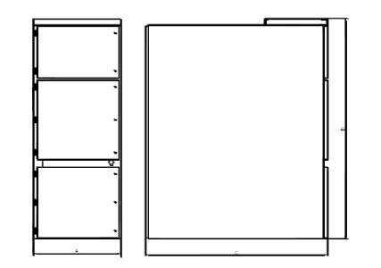
Figure 3KYN28-24KV switch cabinet outline dimensions
A width: (800mm/1000mm)
B height: (2360mm)
C depth: (1820mm)

Figure 4KYN28A-24 (Z) type mounting dimensions
Cabinet width L1=530mm L2=630mm A=800mm 800*1820*2360
Cabinet width L1=730mm L2=830mm A=1000mm 1000*1820*2360
10 transportation and storage
In the course of transportation and storage, we should pay attention to the following points:
10.1 do not flip, invert and suffer from severe vibration, to prevent near the fire source.
10.2 should prevent rain, so as to avoid product moisture.
10.3 shall not be free to remove the electrical products and parts.
11 random files and spare parts
11.1 product qualification certificate;
11.2 packing list;
11.3 factory inspection report;
11.4 instructions for use;
11.5 equipment and spare parts list;
Two 11.6 wiring diagram;
11.7 mid handcart operating the rocking handle, grounding switch operation handle, the storage below the handle and mid handcart transfer vehicle (10 sets of contract units, 5 units each with a set; more than 10 sets for each additional 10 and
1).
Six, ordering instructions
The following information should be provided when ordering:
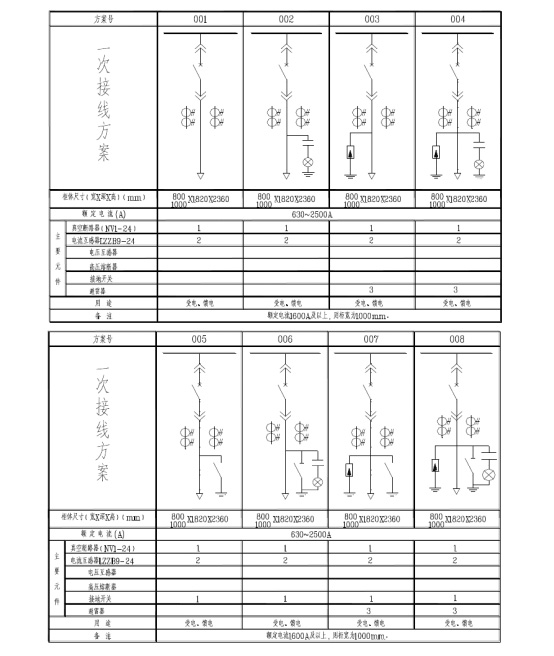
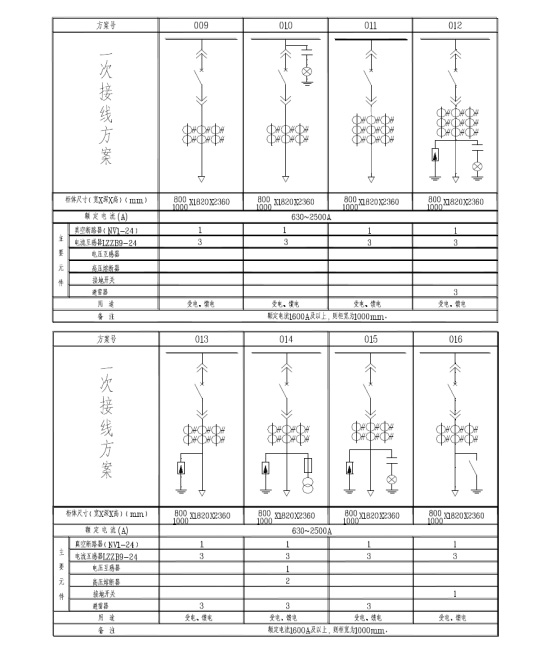
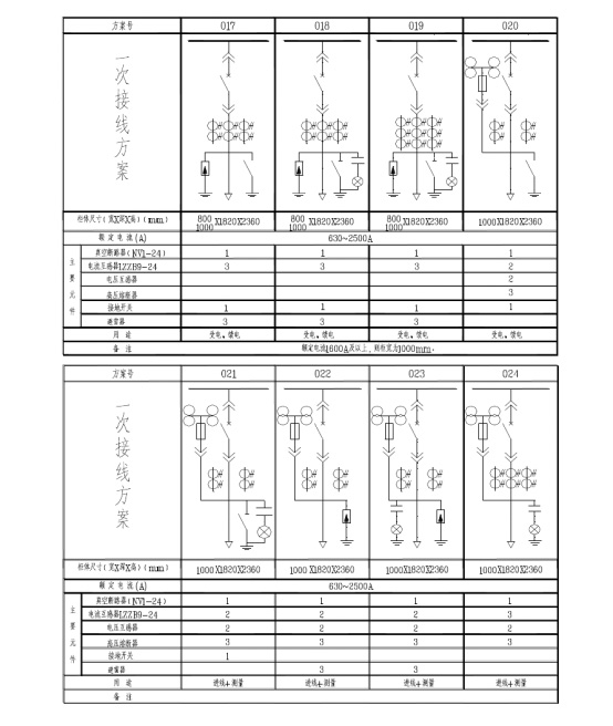
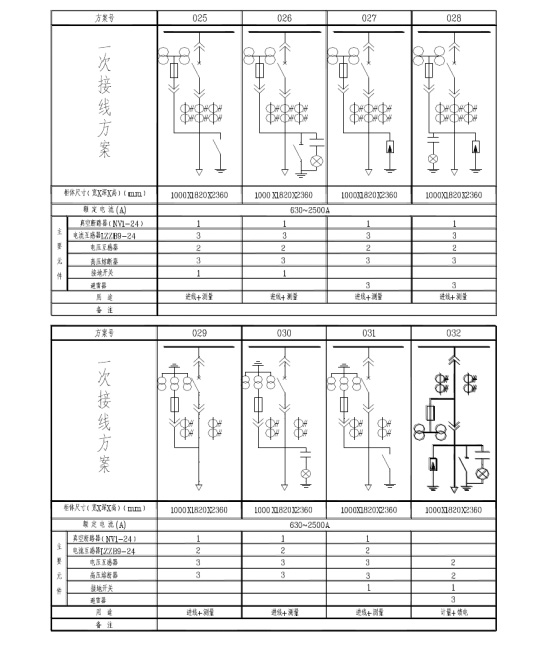
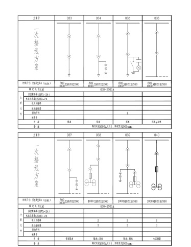
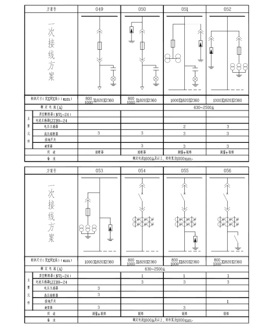
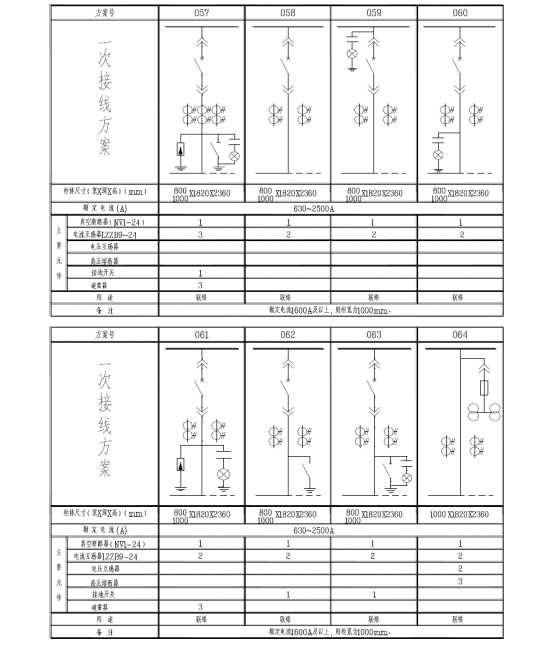
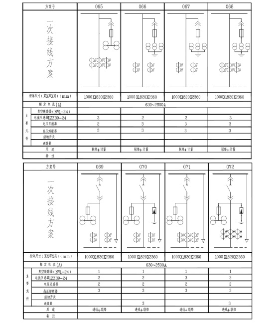
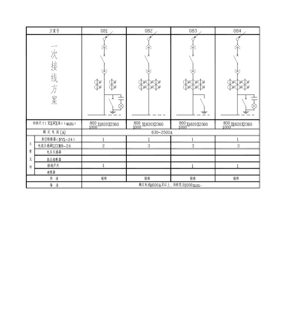
12.1 master plan number and single line system diagram, arrangement and layout;
Two 12.2 wiring diagram, the terminal arrangement diagram, if the terminal layout of the manufacturers in accordance with the layout of the terminal;
12.3 types of switching devices, electrical components, specifications, quantity;
12.4 summary of electrical equipment;
12.5 bus bridge (two column cabinet and bus bridge between StorWall bus bridge) is required to provide the span and height dimensions;
12.6 switching equipment used in special environmental conditions in order to put forward;
12.7 the type and quantity required to be supplied with other or beyond the specified accessories.
Seven, a system diagram